Fiber Optics: Limiting Factors
Created on: Jun 5, 2019
Fiber Optics have greatly increased the speed and density of data transition, with new advancements coming out every year. Most of these advancements are geared to increase distance and signal power by decreasing the affects of Dispersion, Light Source, Frequency, etc.
Light Source
| Light Source | Transmission Distance | Transmission Speed | Transmission Frequency | Applicable Modes | Cost |
|---|---|---|---|---|---|
| Light Emitting Diode (LED) | Short | Low | Wide Spectral Width | MM only | Low |
| Fabry-Perot (FP) Laser | Medium | High | Medium Spectral Width | SM and MM | Moderate |
| Vertical Cavity Surface-Emitting (VCSEL) | Medium | High | Narrow Spectral Width | (1310nm SM) and MM | Low |
| Distributed Feedback (DFB) Laser | Long | Very High | Narrow Spectral Width | Long SM Applications | High |
After reviewing this table, it quickly becomes apparent which Light Sources are most practical for specific uses. For example, DFB would never be use in short Patch Cable applications but it is ideal for Long Distance Transmission. VSCEL has completely triumphed over LED in Data Center applications as the price has dropped significantly in recent years.
Distance
Distance is one of the biggest limiting factors for Fiber Optic Data Transmission. Light eventually looses its power after traveling through the fiber, this can be do to resistance, attenuation, dispersion and many other factors that limit Fiber Optics. The chart below represents the various speeds vs. distances when comparing each Fiber Type.
| Mode | Type | Core/ Cladding (um) | Fast Ethernet (100Mb) | Gigabit (GbE) | 10 Gigabit (10GbE) | 40 Gigabit (GbE) | 100 Gigabit (GbE) | 40G (SWDM4) | 100G (SWDM4) |
| Multimode | OM1 | 62.5/125 | 2km | 275m | 32m | - | - | - | - |
| Multimode | OM2 | 50/125 | 2km | 550m | 82m | - | - | - | - |
| Multimode | OM3 | 50/125 | 2km | 800m | 300m | 100m | 100m | 240m | 75m |
| Multimode | OM4 | 50/125 | 2km | 1100m | 400m | 150m | 150m | 350m | 100m |
| Multimode | OM5 | 50/125 | 2km | 1100m | 400m | 150m | 150m | 440m | 150m |
| Single Mode | OS1/OS2 | 9/125 | 40km | 100km | 40km | 40km | 40km | - | - |
As the table clearly demonstrates, Single Mode Fiber is the clear winner for distance purposes.
Dispersion
There are two main types of Dispersion that affect Fiber the most significantly Chromatic and Modal.
Chromatic Dispersion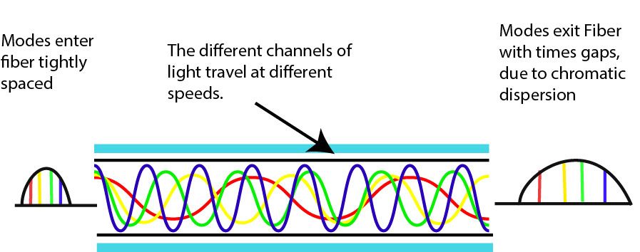 Chromatic Dispersion can best be described as the signal becoming spread out over the length of the fiber because light travels at different speeds depending on its frequency.
Modal Dispersion 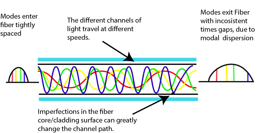 Modal Dispersion affects the signal for the same reason, except it is caused by light traveling in different lanes of the fiber which will refract differently based on the imperfections and Index of Refraction specific to the section it travels in. This causes Dispersion of the light waves traveling down the fiber and the affect increases with distance. This type of Dispersion only happens on Multimode Fiber, which is the one of the main reasons why Singlemode is chosen for long distance applications.
Optical Insertion Loss
Optical Insertion Loss(IL) is the measurement of lost light from end to end of a fiber cable and mainly occurs at the point of contact of Connectors and Splices. This is often attributed to misalignment, contamination or poorly manufactured ferrules. Fusion splices are advocated in some cases because of this, however this Insertion Loss is is marginal (.1dB) Engineers have designed several types of Ferrule Head Styles to combat with Insertion Loss. Another culprit for IL is micro bending and macro bending. Micro Bending refers to small scale bends in the fiber, usually caused by other conductors in the conduit or small pressure points along the fiber where exterior objects flex the fiber core. These bends are not large enough to see with the human eye, and normally go physically undetected. There is no current effective test for micro bending. Macro bending refers to large bends around corners and into patch panels. These bends are anticipated in installation, and the total loss can be tested by measuring the necessary radius of the turn. To help combat this IL, we stock Bend-Insensitive Single Mode Fiber Cables so that you will not have to worry about such performance losses in your installation. Although connectors are the biggest contributing factor of Insertion Loss, they are a necessary evil and steps can be taken to reduce your overall IL. Talk with engineers/designers and try to reduce your total number of components and not to skimp on quality, buying cheap fiber and components can cost much more down the line. Talk to your installation crew and stress the importance of cleanliness when handling and connecting the Fiber Optic Connectors. If your fiber cable is too long for the installation, use the biggest coils possible to reduce refraction through the cladding. When ever possible during installation push the cable in, and when pulling is needed do not exceed the tensile load of the cable.
Optical Return Loss
Optical Return Loss (RL), also known as reflectance, is when the light is reflected back towards the source. This can occasionally not only cause latency, but also prevent the original laser source from transmitting correctly. RL is measured in decibel (dB) and is expressed as a negative since the signal is reflected. For example 40dB of Optical Return Loss is displayed as -40dB. Some systems can handle a higher RL up to 40dB (.01% of light), how ever more sensitive systems such as Fiber To The House (FTTH) requires no more that -60dB (.000005%). In order to achieve these low Return Loss levels, Angle Ferrule Connectors (APC) must be used. Both IL and RL should be factored into your network planning. To help prevent RL as much as possible, minimize bends in a fiber run and ensure that there is no torsion or strain on the cable. There are two ways to measure Return Loss. One uses a light source and a power meter with an optical CW reflectometer (OCWR), and the other method uses an Optical Time Domain Reflectometer (OTDR). To learn more about how to measure Optical Return Loss, check out the Fiber Optic Association's great blog on the topic.

Author:
Brian Sackett
Marketing & Development