Featured Products
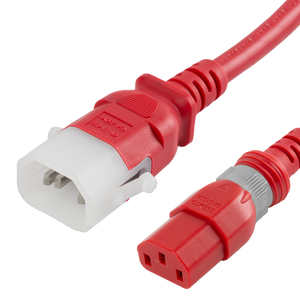
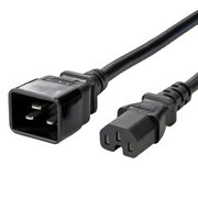
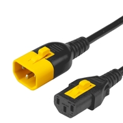
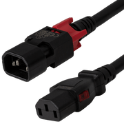
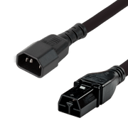
Dual-Lock / SecureLock
Dual-Locking power cords work with ServerTech, Raritan, and any other P-Lock compatible receptacle. With a universal lock on the female end, you can ensure that no accidental disconnects occur on either the PDU or device side of the cable. Available in many colors and lengths and in all IEC 60320 configurations.
Show Now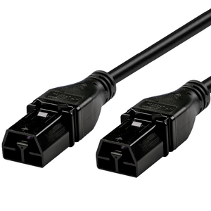
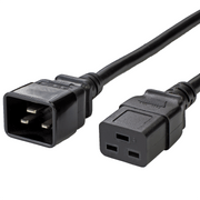
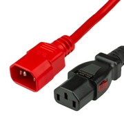
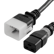
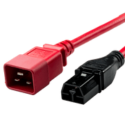
Anderson Saf-D-Grid
To minimize the risk of personal contact with a hazardous voltage, safety standards require protection against finger access to live parts 50V and above. Unlike IEC 60320 connectors, Saf-D-Grid plug & receptacle connectors both feature a Touch Safe shell with shock protection and both pass UL & IEC finger probe (plug & receptacle) and 3mm probe tests (receptacle). Further, with regard to power density Saf-D-Grid connectors are rated to carry up to 2x more current and 1.6x more voltage than the standard IEC 60320 C20.
Show Now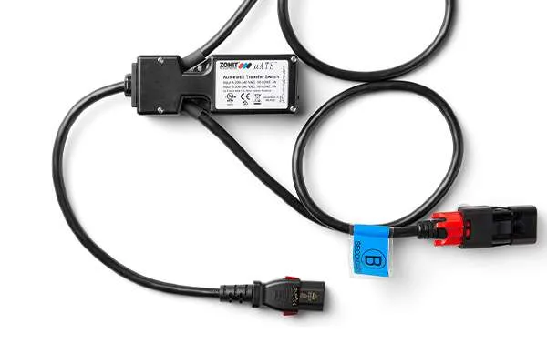
Zonit Z-ATS
The Z-ATS Micro ensures uninterrupted power supply to your servers by offering A and B redundant power sources to single-corded devices. This maximizes server power supply and minimizes the risk of cascading failures to keep your data center operations running smoothly.
Show Now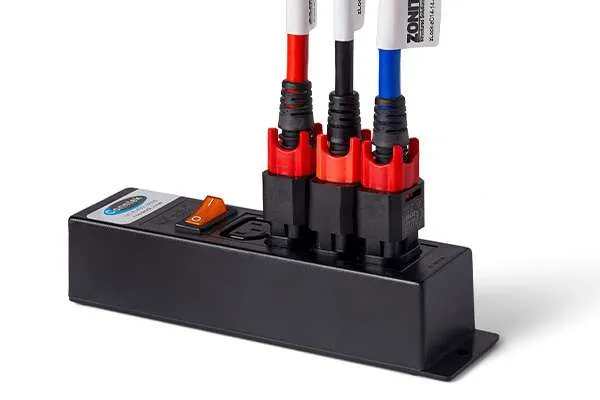
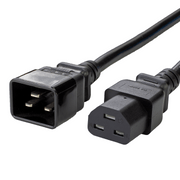
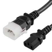
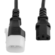
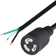
Zonit Z-Lock
Z-LOCK provides a seamless experience with advanced locking technology that requires no clips or extra hardware. It's a straightforward, simple, and effective solution to keep your power cords securely connected.
Show Now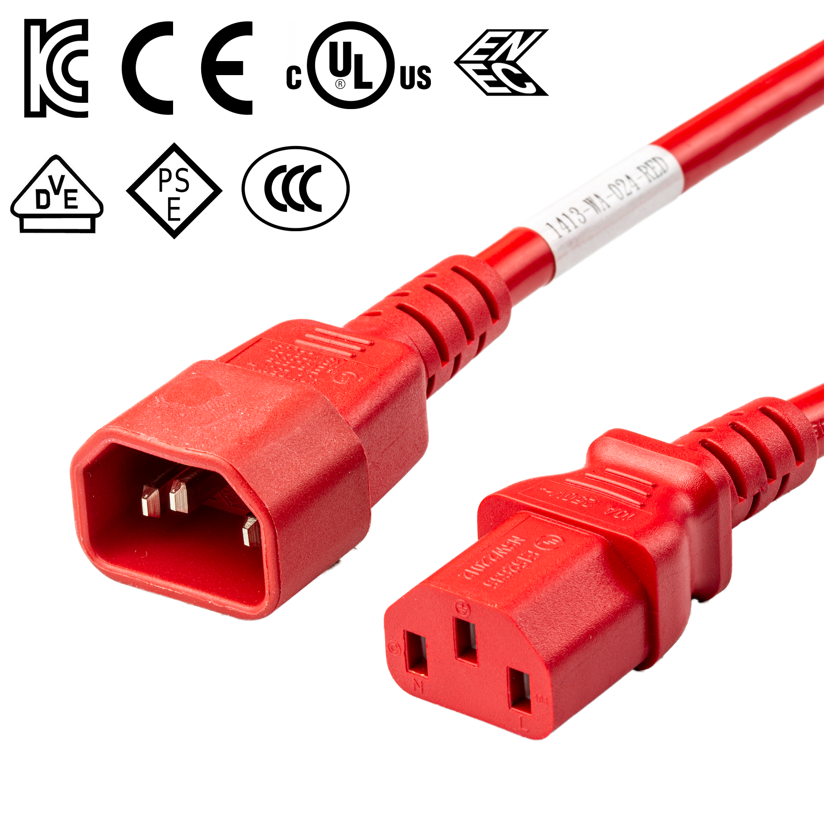
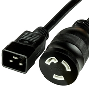
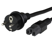
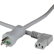
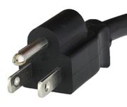
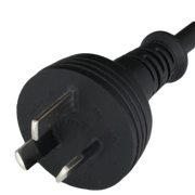
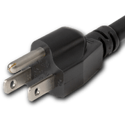
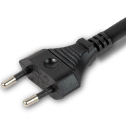
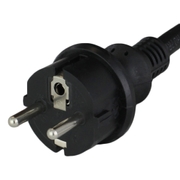
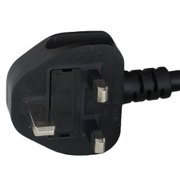
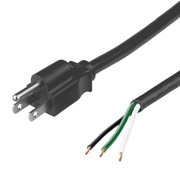
Global Power Cords
Global Power Cords allow you to spec one part number and deploy your servers globally, ensuring you are in compliance with country approval requirements such as UL, PSE, VDE, ENEC, SAA, KC, CCC
Show Now


.jpg?w=180)

.jpg?w=180)
About Us
Technical Support
Need help finding a product, understanding a specification, or figuring out what you need for your installation? We have you covered.
Engineering Services
Custom engineered solutions for any project, from OEM manufacturing services to Data Center PDU Whips.
An Extension of You
We strive to integrate as closely as possible into your company, allowing you unprecedented visibility and control into how WoCo services you.